TISC 2024 | Hardware isnt that Hard!
Published on: February 6, 2025
20 min read · Posted by Baba is Dead
Challenge Details
Description
Category
Hardware Hacking
Difficulty
Medium
Topics
Competition
TISC 2024
Author
Baba is Dead
Shucks... it seems like our enemies are making their own silicon chips??!? They have decided to make their own source of trust, a TPM (Trusted Platform Module) or I guess their best attempt a
Writeup
About the Challenge
This challenge involves sending data through a TPM (Trusted Platform Module).
A TPM is a hardware chip that provides security functions, such as storing cryptographic keys and ensuring system integrity. In this case, the TPM connects to other devices using the I2C bus and handles security operations internally. Your mission is to uncover any weaknesses in this TPM and extract its secrets, despite the safeguards it has in place.
Connecting to the service, we are greeted with this message
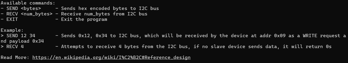
In I2C Communication, the first byte of transmission specified both the 7-bit address of the target device and the read/write bit. The least significant bit indicates wheter the operation is a read or write request. 0 for write, and 1 for read. In the example above, SEND 12 34 sends a WRITE request to the device at 0x09. This is because 12 in hex converts to 00010010 in binary. The least(last) significant bit (0) tells us that it is a WRITE Request. The remaining bits 0001001 tells us the address of the target device, which is 0x09 in hexadecimal.
With this knowledge, we can begin reversing the flash dump provided to us.
Reversing the Flash Dump
Ghidra on it's own is not sufficient to reverse a flash dump. We need an additional library, Ghidra-Esp32-Flash-Loader to fully reverse the code.
Loading the file, it is not immediately clear where our entry point is. There are several ways to determine where the entry point is.
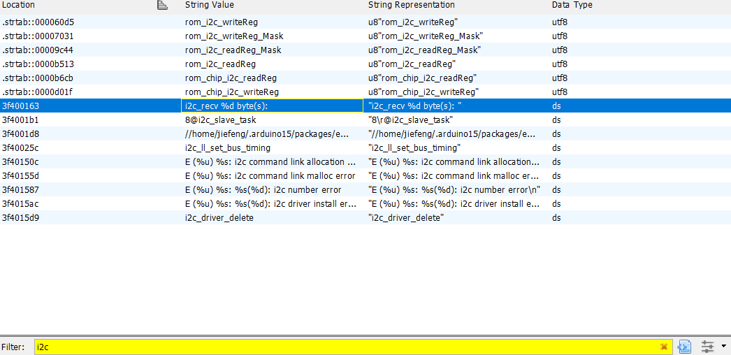
I searched for some keywords in Ghidra, and searching for the string "i2c" just so happened to bring me to a function that seemed to be the entry point of the slave device.
Heres the decompiled code of the main function. I've renamed some functions and variables, so this might not be what you see when you first reverse the binary.
void main(uint bytes_received)

{
  byte RNGNo;
  uint uVar1;
  int i;
  int in_WindowStart;
  undefined auStack_30 [12];
  uint uStack_24;
  int alligned_memory_offset_auStack_30;
  int baseAdressofauStack_30;
  byte flagChar;

  memw();
  memw();
  uStack_24 = zero;
  print?(&DAT_3ffc1ecc,"i2c_recv %d byte(s): ",bytes_received);
  baseAdressofauStack_30 = (uint)(in_WindowStart == 0) * (int)auStack_30;
  alligned_memory_offset_auStack_30 =
       (uint)(in_WindowStart != 0) * (int)(auStack_30 + -(bytes_received + 0xf & 0xfffffff0));
  transf(&DAT_3ffc1cdc,baseAdressofauStack_30 + alligned_memory_offset_auStack_30,bytes_received) ;
  printhex(baseAdressofauStack_30 + alligned_memory_offset_auStack_30,bytes_received);
  if (0 < (int)bytes_received) {
    uVar1 = (uint)*(byte *)(baseAdressofauStack_30 + alligned_memory_offset_auStack_30);
    if (uVar1 != 0x52) goto LAB_400d1689;
    memw();
    DAT_3ffc1c80 = 0;
  }
  while( true ) {
    uVar1 = uStack_24;
    bytes_received = zero;
    memw();
    memw();
    if (uStack_24 == zero) break;
    FUN_40082818();
LAB_400d1689:
    if (uVar1 == 0x46) {
      i = 0;
      do {
        memw();
        flagChar = (&FLAG)[i];
        RNGNo = RNG();
        memw();
        (&DAT_3ffc1c80)[i] = flagChar ^ RNGNo;
        i = i + 1;
      } while (i != 16);
    }
    else if (uVar1 == 0x4d) {
      memw();
      DAT_3ffc1c80 = DAT_3ffbdb7a;
      memw();
    }
    else if ((bytes_received != 1) && (uVar1 == 0x43)) {
      memw();
      flagChar = rwip_heap_env
                 [*(byte *)(baseAdressofauStack_30 + alligned_memory_offset_auStack_30 + 1) + 0x22 dd
                 ];
      RNGNo = RNG();
      memw();
      (&DAT_3ffc1c1f)[*(byte *)(baseAdressofauStack_30 + alligned_memory_offset_auStack_30 + 1)] =
           flagChar ^ RNGNo;
    }
  }
  return;
}
We can then analyse the code to determine where the flag is being used. After inspecting the different memory pointers, the renamed &FLAG memory pointer stood out the most. When I visited the memory stored at this FLAG pointer, we see some suspicious data stored:

This seems to be the placeholder for the flag. We can then take a look at where this memory is being accessed:
if (uVar1 == 0x46) {
    i = 0;
    do {
    memw();
    flagChar = (&FLAG)[i];
    RNGNo = RNG();
    memw();
    (&DAT_3ffc1c80)[i] = flagChar ^ RNGNo;
    i = i + 1;
    } while (i != 16);
}
It seems that when a certain variable uVar1 is 0x46, the flagChar will be XORed with a Random Number. Then, the result of the XOR is appended to DAT_3ffc1c80. We can deduce that DAT_3ffc1c80 likely contains the data that is sent to the TPM. We will confirm this later.
To find out what uVar1 contains, we can take a look at the code run prior to this.
print?(&DAT_3ffc1ecc,"i2c_recv %d byte(s): ",bytes_received);
baseAdressofauStack_30 = (uint)(in_WindowStart == 0) * (int)auStack_30;
alligned_memory_offset_auStack_30 =
    (uint)(in_WindowStart != 0) * (int)(auStack_30 + -(bytes_received + 0xf & 0xfffffff0));
transf(&DAT_3ffc1cdc,baseAdressofauStack_30 + alligned_memory_offset_auStack_30,bytes_received) ;
printhex(baseAdressofauStack_30 + alligned_memory_offset_auStack_30,bytes_received);
The above seems to be some debug statement. The first line print?(&DAT_3ffc1ecc,"i2c_recv %d byte(s): ",bytes_received); outputs the number of bytes being received through the i2c connection. Since bytes_received will be sustituted into the %d portion of the above string, we can deduce that bytes_received is the number of bytes the i2c connection receives.
The last line printhex(baseAdressofauStack_30 + alligned_memory_offset_auStack_30,bytes_received); prints out the hex data of what's stored at baseAdressofauStack_30 + alligned_memory_offset_auStack_30, which immediately follows the i2c_recv %d byte(s): string above.
We can thus conclude that baseAdressofauStack_30 + alligned_memory_offset_auStack_30 contains our sent bytes.
if (0 < (int)bytes_received) {
uVar1 = (uint)*(byte *)(baseAdressofauStack_30 + alligned_memory_offset_auStack_30);
if (uVar1 != 0x52) goto LAB_400d1689;
memw();
DAT_3ffc1c80 = 0;
}
Here, we can see that uVar1 is equal to baseAdressofauStack_30 + alligned_memory_offset_auStack_30, which we concluded earlier was our sent bytes. uVar1 is not touched after this. Hence, we can conclude that uVar1 contains our sent bytes through the TPM to the slave device.
This means that if we send the bytes 0x46 using a WRITE command to the correct address, then receive using a READ command, we should see some data being received by the TPM.
Testing
We do not know which address the slave is located at. We can craft a simple script to brute force this.
from pwn import remote

# Connect to the remote I2C device
r = remote('chals.tisc24.ctf.sg', 61622)

# Read initial response from the server (to sync with the server)
r.recvuntil(b"Read More: https://en.wikipedia.org/wiki/I%C2%B2C#Reference_design")
r.recvline()
r.recvline()
for address in range(0,128):
    WRITECMD = address << 1 | 0 # Address is shifted left by 1 and the least significant bit is set to 0 (WRITE)
    READCMD = address << 1 | 1 # Address is shifted left by 1 and the least significant bit is set to 1 (READ)
    r.send(f"SEND {WRITECMD:02X} 46\n".encode())
    r.send(f"SEND {READCMD:02X} 46\n".encode())
    r.send(f"RECV 32\n".encode())
    response = r.recvline().decode().strip().split(" ")
    data = filter(lambda x: x != ">", response)
    # if data is not empty, the device is found
    for i in data:
        if i != "00":
            print(f"Device found at address {address:02X}: {" ".join(response)}")
            break

r.close()
The above code guesses each possible slave address. Since the slave address is 7 bits long, the address ranges from 0 to 128. At each address, we send a WRITE command with the payload "46" as discussed earlier. Then, we send a READ command. Afterwards, if we find an address that received non-zero bytes, we know that our logic previously was correct. Running the code, we get the following output:
Device found at address 69: > > > 2b 8f be 08 a1 b8 f1 d4 c6 69 98 6d 9e ee 66 37 00 00 00 00 00 00 00 00 00 00 00 00 00 00 00 00
The device is located at address 69. Now, we simply need to decrypt the output we received.
Decrypting the Output
As mentioned before, the flag is XOR'ed with Random values. We can investigate the RNG function to see if it truly is random or not.
ushort RNG(void)
{
  _RNG_NUM = _RNG_NUM << 7 ^ _RNG_NUM;
  _RNG_NUM = _RNG_NUM >> 9 ^ _RNG_NUM;
  _RNG_NUM = _RNG_NUM << 8 ^ _RNG_NUM;
  return _RNG_NUM;
}
This RNG Number doesn't look so random after all! A bunch of bitwise shifts are being performed, before being XORed with the original RNG Number. This means that the genaration of each RNG number is dependant on the previous, meaning we only need to guess the starting RNG number.
We should also note that the RNG nubmer is only 2 bytes long, ranging from 0 to 65536. This means that we do not have to search through many numbers.
Crafting a script to bruteforce the correct starting RNG Number:
_RNG_NUM = 0 # Initial seed value
def RNG():
    global _RNG_NUM
    # It should be noted that _RNG_NUM is a 2 byte value. At each step, we must ensure that it remains a 2 byte value.
    # Perform the operations without restricting the intermediate results to a byte
    _RNG_NUM = (_RNG_NUM << 7) ^ _RNG_NUM  # Shift left by 7 and XOR with itself
    _RNG_NUM = (_RNG_NUM & 0xFFFF)  # Apply the 0xFFFF mask to ensure the result is 2 bytes long
    _RNG_NUM = (_RNG_NUM >> 9) ^ _RNG_NUM  # Shift right by 9 and XOR with itself
    _RNG_NUM = (_RNG_NUM & 0xFFFF)  # Apply the 0xFFFF mask to ensure the result is 2 bytes long
    _RNG_NUM = (_RNG_NUM << 8) ^ _RNG_NUM  # Shift left by 8 and XOR with itself

    # Finally, apply the 0xFF mask to ensure the final result is a byte (8 bits)
    _RNG_NUM = _RNG_NUM & 0xFFFF
    return _RNG_NUM & 0xFF


# Example output (DAT_3ffc1c80) you received from the device
hex_values = "2b 8f be 08 a1 b8 f1 d4 c6 69 98 6d 9e ee 66 37".split(" ")
print(len(hex_values))

# Convert each hexadecimal string to an integer
output = [int(x, 16) for x in hex_values]
print(output)

for i in range(0,256*256):
    _RNG_NUM = i
    decrypted_flag = []
    # attempt to decrypt the flag using each starting RNG Number
    for i in range(len(output)):
        flag_byte = output[i] ^ RNG()
        decrypted_flag.append(flag_byte)
    if 'TISC' in ''.join(chr(b) for b in decrypted_flag):
        print("RNG seed:", _RNG_NUM)
        print("Decrypted flag:", ''.join(chr(b) for b in decrypted_flag))
        break
Running the code, we can retreive our flag.
Flag
TISC{hwfuninnit}
Resources
Afterword
hwnotfuninnit. I accidentally stumbled upon the solution when trying to bruteforce the first byte. I didn't really understand how I2C communication worked until after the CTF, when I wrote this writeup.
I don't normally touch rev, but this is one of the rare instances I'm forced to do it so ;-;
Please login to comment
Comments
No comments yet